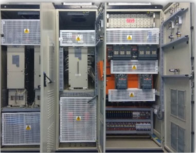
A1000 HHP
A1000 HHP is a high horse power AC drive
The drive is of modular design with separate converter and inverter sections installed in a common enclosure. These sections can be paralleled to increase capacity to 2250 amps at 400 and 690 volts.
- The Desired power level is achived by adding converter/Inverter module in parallel
- Slide-rail construction techniques permit easy access for maintenance, removal or replacement
- The A1000HHP features a standard non-regenerative front end and easily support at a 12pulse for reduced harmonic
- A regenerative front end is available as an option, which will meet IEEE-519 harmonic specifications.
- The drive incorporates versatile control modes in one product; traditional V/Hz, open loop vector, and closed loop flux vector. Open loop for PM , Advanced open loop for PM. Closed loop for PM
- Optional interface boards provide a wide range of control, monitoring, and diagnostic communication capabilities for integration from plant floor to supervisory level systems.
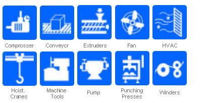
- The drive provides increased versatility in installations of up to 1350kW for 400V & 1750 for 690V, including pumps and Industrial fans, chillers, pulp and paper manufacturing, mining industry conveyors, rock crushers and extruders,Mining, Metals , Oil and gas etc

A1000 HHP Modular Drive
- 460 V , 263 to 1200 kW (HD)
- 575/690 V, 300 to 1500 kW (HD)
Application

Elevator Drive
A1000 HHP Modular Drive
| EUJ71001x:480V | EUJ71002x:575/690V | |||||||||||
| Number of Inverter Modules | 1 | 2 | 3 | 4 | 5 | 1 | 2 | 3 | 4 | 5 | ||
| Max motor capacity (kW) | Heavy Duty | 263 | 525 | 750 | 938 | 1200 | 300 | 600 | 938 | 1200 | 1500 | |
| Normal Duty | 300 | 600 | 750 | 1125 | 1350 | 335 | 675 | 1050 | 1350 | 1688 | ||
| Input | Rated Input current (A) | Heavy Duty | 452 | 894 | 1272 | 1588 | 2027 | 473 | 939 | 1461 | 1864 | 2326 |
| Normal Duty | 514 | 1020 | 1272 | 1901 | 2278 | 528 | 1054 | 1633 | 2095 | 2615 | ||
| Output | Rated output capacity (kVA) | Heavy Duty | 330 | 640 | 960 | 1280 | 1600 | 500 | 960 | 1440 | 1920 | 2400 |
| Normal Duty | 380 | 720 | 1080 | 1440 | 1800 | 560 | 1080 | 1620 | 2160 | 2690 | ||
| Rated output current | Heavy Duty | 414 | 800 | 1200 | 1600 | 2000 | 414 | 800 | 1200 | 1600 | 2000 | |
| Normal Duty | 466 | 900 | 1350 | 1800 | 2250 | 466 | 900 | 1350 | 1800 | 2250 | ||
| Overload tolerance | Heavy Duty | 150% of rated output current for 60 seconds | 150% of rated output current for 60 seconds | |||||||||
| Normal Duty | 120% of rated output current for 60 seconds | 120% of rated output current for 60 seconds | ||||||||||
| Carrier Frequency | 2kHz | 2kHz | ||||||||||
| Max output voltage (V) | 3 phase 380V~480 (relative to input voltage) | 3 phase 500V~690 (relative to input voltage) | ||||||||||
| Max output frequency (Hz) | 150Hz | 150Hz | ||||||||||
| Motor Power | kW | Heavy Duty | 261 | 522 | 745 | 1080 | 1341 | 373 | 782 | 1155 | 1565 | 1937 |
| Normal Duty | 298 | 596 | 894 | 1192 | 1490 | 447 | 857 | 1304 | 1751 | 2198 | ||
| Motor Average Current Rating | Amps | Heavy Duty | 397 | 747 | 1067 | 1450 | 1920 | 400 | 800 | 1105 | 1533 | 1924 |
| Normal Duty | 451 | 800 | 1281 | 1708 | 2135 | 450 | 890 | 1280 | 1740 | 2212 | ||
| Power Supply Characteristics | Rated voltage / Rated frequency | AC: 380~480V 50/60 Hz DC: 510~680 V |
AC: 500~690 V 50/60 Hz DC: 675~975 V |
|||||||||
| Allowable voltage fluctuation | -15~ +10% | -15~ +10% | ||||||||||
| Allowable frequency fluctuation | ±5% | ±5% | ||||||||||
| Power Supply kVA | Heavy Duty | 420 | 820 | 1170 | 1460 | 1860 | 630 | 1240 | 1930 | 2460 | 3060 | |
| Normal Duty | 480 | 940 | 1170 | 1740 | 2090 | 700 | 1390 | 2150 | 2760 | 3440 | ||
| Item | Specification | |
| Control Method | V/F Control, V/F Control with PG Open Loop Vector Control Closed Loop Vector Control with PG Advanced Closed Loop Vector Control |
|
| Frequency Control Range | 0.01 Hz to 150 Hz | |
| Frequency Accuracy (temperature fluctuation) | Digital Reference Input: +/- 0.01% of the max. output frequency (-10 to +40 degrees C) Analog reference Input: +/- 0.1% of the max. output frequency (-10 to +40 degrees C) |
|
| Frequency Setting Resolution | Digital Reference Input: 0.01 Hz Analog Reference Input: 0.03 Hz at 60 Hz (1/2048 of max. output frequency setting, 11 bit plus sign) |
|
| Output Frequency Resolution | 0.001 Hz | |
| Frequency Reference Setting Signal | -10 to +10 Volts, 0 to +10 Volts, 4 to 20 mAmps, pulse train | |
| Starting Torque | V/F, V/F with PG: 150% at 3 Hz Open Loop Vector, Advanced Open Loop Vector: 200% at 0.3 Hz Closed Loop Vector: 200% at 0 RPM |
|
| Speed Control Range | V/F, V/F with PG: (1:40) Open Loop Vector, Advanced Open Loop Vector: (1:200) Closed Loop Vector: (1:1500) |
|
| Speed Control Accuracy | Open Loop Vector: +/- 0.2% (25 degrees C +/- 10 degrees C) Closed Loop Vector: +/- 0.02% (25 degrees C +/- 10 degrees C) | |
| Speed Response | Open Loop Vector: 10 Hz (25 degrees C +/- 10 degrees C) Closed Loop Vector: 50 Hz (25 degrees C +/- 10 degrees C) | |
| Torque Limit | Separate limit settings in four quadrants for OLC, CLV, Advanced CLV | |
| Accel / Decel Time | 0.00 to 6000.0 seconds (4 selectable combinations of independent accel and decel settings) | |
| Braking Torque | Based on external braking or regenerative system | |
| V / F Characteristics | User selected programs and pre set V / F patterns are available | |
| Main Control Functions | Torque Control, Droop Control, Speed/torque Control Switching, Feed Forward Control, Zero ServoFunction, Momentary Power Loss Ride-Thru, Speed Search, Overtorque/Undertorque Detection, Torque Limit, 17 Step Speed (max), Accel/decel Switch, S-curve Accel/decel, 3-wire Sequence, Auto-tuning (rotational, stationary tuning), Dwell, Cooling Fan on/off Switch, Slip Compensation, Torque Compensation, Frequency Jump, Upper/lower Limits for Frequency Reference, DC Injection Braking at Start and Stop, Overexcitation Braking, High Slip Braking, PID Control (with sleep function), Energy Saving Control, MEMOBUS/Modbus Comm. (RS-422/485 max, 115.2 kbps), Fault Restart, Application Presets, DriveWorksEZ (customized function), Overexcitation Deceleration, Inertia (ASR) Tuning, Overvoltage Suppression, High Frequency Injection |
|
| Motor Protection | Motor overheat protection based on output current | |
| Instantaneous Overcurrent Protection | Drive stops when output current exceeds 200% of rated output current (heavy duty rating) | |
| Overcload Protection | Drive stops after 60 seconds at 150% of rated output current (heavy duty rating) | |
| DC Bus Overvoltage Protection | 460V input | Stops when the DC bus is higher than approximately 820 Vdc |
| 575V input | Stops when the DC bus is higher than approximately 1040 Vdc | |
| 690V input | Stops when the DC bus is higher than approximately 1196 Vdc | |
| DC Bus Under Voltage Protection | 460V input | Stops when the DC bus is lower than approximately 380 Vdc |
| 575V input | Stops when the DC bus is lower than approximately 475 Vdc | |
| 690V input | Stops when the DC bus is lower than approximately 570 Vdc | |
| Momentary Power Loss Ride Through | Immediately stops after a 15 mSecs or longer power loss (default). Continuous operation during a power loss shorter than 2 seconds (standard) | |
| Heatsink Overheat Protection | Thermistor | |
| Stall Prevention | Stall prevention is available during acceleration/deceleration and during constant speed operation | |
| Ground Fault Protection | Protection by electronic circuit | |
| Charge LED Indicator | Charge LED remains on until DC bus voltage becomes 50 V or less | |
| Discharging Time | Approximately 10 minutes or until DC bus voltage becomes 50 V or less | |
| Environment | Area of Use | Indoors, Inside a cabinet or panel |
| Ambient Operating Temperature | -10~45° c | |
| Humidity | 95% or less (non condensing) | |
| Storage Temperature | -20~60° | |
| Altitude | Up to 1000 meters | |
| Vibration | 10 Hz~55 Hz, 2.0m/s2 | |
| Protection Design | IP00 | |
| Safety Standard | UL 508C | |