D1000
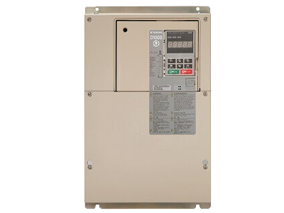
The D1000 regenerative converter unit from YASKAWA saves energy and space. Suitable for both regenerative individual drives and systems of inverter drives, servo axes or robots, the D1000 feeds excess braking energy back into the grid instead of converting it into heat . This not only reduces energy consumption and cost but also contributes to the protection of our environment.
Features
- Sinusoidal input current reduces the strain on the power supply system (lines, transformers)
- Low energy consumption due to common DC bus systems – the braking energy of one drive is consumed by other drives in the system
- Recovered energy can be used by other consumers in the same facility, lowering the total energy consumption of the facility
- Less installation space as braking transistors and resistors are not required
- Less waste heat reduces the workload of the ventilation system
- Requires less maintenance work than systems with braking resistors
- Lowers the total operating costs of the system
- Increased system reliability thanks to stable DC link voltage, even with different or fluctuating input voltages
Applications with Energy Recovery


Power Regenerative Drive
Ratings:
- 3 ~ 200V, 3.5kW to 105kW
- 3 ~ 400V, 3.5kW to 300kW
Applications for Low Harmonics

Applicable Models
- A1000
- V1000
- J1000
- Varispeed G7
- L1000A
- GA700
- GA500
- Servo Drives
Power Regenerative Converter
200V Class
| D1000 Model No | Pout(kW) | IDC(A) | IAC(A) |
|---|---|---|---|
| CIMR-DD2A0005 | 3.7 | 15 | 15 |
| CIMR-DD2A0010 | 7.5 | 30 | 29 |
| CIMR-DD2A0020 | 15 | 61 | 57 |
| CIMR-DD2A0030 | 22 | 91 | 83 |
| CIMR-DD2A0050 | 37 | 152 | 140 |
| CIMR-DD2A0065 | 55 | 197 | 200 |
| CIMR-DD2A0090 | 75 | 273 | 270 |
| CIMR-DD2A0130 | 110 | 394 | 400 |
400V class
| D1000 Model No | Pout(kW) | IDC(A) | IAC(A) |
|---|---|---|---|
| CIMR-DD4A0005 | 3.7 | 8 | 8 |
| CIMR-DD4A0010 | 7.5 | 15 | 16 |
| CIMR-DD4A0020 | 15 | 30 | 30 |
| CIMR-DD4A0030 | 22 | 45 | 43 |
| CIMR-DD4A0040 | 30 | 61 | 58 |
| CIMR-DD4A0060 | 45 | 91 | 86 |
| CIMR-DD4A0100 | 75 | 152 | 145 |
| CIMR-DD4A0130 | 110 | 197 | 210 |
| CIMR-DD4A0185 | 160 | 280 | 300 |
| CIMR-DD4A0270 | 220 | 409 | 410 |
| CIMR-DD4A0370 | 315 | 561 | 560 |
| CIMR-DD4A0630 | 560 | 955 | 1040 |
| Control Characteristics | |
| Product | D1000 |
| Type | Power Regerative Converter |
| Rated Output Voltage (dependent on input) | Three Ph 200V Class : 330 Vdc Three Ph 400V Class : 660 Vdc |
| Compatibe Inverter Types | A1000, V1000, J1000, GA700, GA500, G7, L1000A, Servo Drives & All conventional Inverters (with a DC Bus), |
| Control Methods | Sine wave PWM |
| Environmental Factors | |
| Ambient Temperature | −10 to +50°C (IP00/IP20/Open Type enclosure) |
| Altitude | Up to 1000 meters (derating required at altitudes from 1000 m to 3000 m) |
| Humidity | 95% RH or less (no condensation) |
| Shock | 2A0005 to 2A0050, 4A0005 to 4A0100) 10 to 20 Hz : 9.8 m/s2, 20 to 55 Hz : 5.9 m/s2 (2A0065 to 2A0130, 4A0130 to 4A0370) 10 to 20 Hz : 9.8 m/s2, 20 to 55 Hz : 2.0 m/s2 (4A0630) 10 to 20 Hz : 5.9 m/s2, 20 to 55 Hz : 2.0 m/s2 |
| Area of Use | Indoor (Protected from corrosive gasses and dust) |
| Protection Features | |
| Fuse Burnout | Operation stops if the fuse burns out. |
| Momentary Overcurrent Protection |
Unit stops when input current exceeds 250%. |
| Overload Protection | Operation stops after 60 s at 150% of rated output current. Operation stops after 3 s at 200% of rated output current. |
| Overvoltage Protection | 200 V Class: Stops when input voltage exceeds approx. 227 Vac, Output: Stops when DC bus voltage exceeds approx. 410 Vdc 400 V Class: Stops when input voltage exceeds approx. 554 Vac, Output: Stops when DC bus voltage exceeds approx. 820 Vdc |
| Undervoltage Protection | 200 V class: Stops when input voltage falls below approx. 150 Vac; Output: Stops when DC bus voltage falls below approx. 190 Vdc 400 V class: Stops when input voltage falls below approx. 300 Vac; Output: Stops when DC bus voltage falls below approx. 380 Vdc |
| Momentary Power Loss Ride-Thru |
Immediately stops after Momentary Power Loss is detected. |
| Heatsink Overheat Protection |
Protection by thermistor |
| Ground Fault Protection | Protection by electronic circuit |
| Charge LED | Charge LED illuminates when DC bus voltage is more than 50 V. |
| Power Specifications | |
| Rated input Voltage/Frequency | 400V Class: 380 to 480 Vac 50/60 Hz 200V Class : 200 to 240 Vac 50/60 Hz |
| Allowable Voltage Fluctuation |
−15% to 10% |
| Allowable Frequency Fluctuation |
±2% |
| Common Specifications | |
| Multi Function Digital Inputs | 8 Digital Inputs ( NPN or PNP ) . |
| Multi Function Digital Outputs | 1 Programmable Relay M1-M2 (250 Vac, max. 1 A; 30 Vdc, max 1 A (min. 5 Vdc, 10 mA)), 1 fault relay MA-MB-MC, 2 photocouplers P1,P2 (48 Vdc, max 50 mA) |
| Multi Function Analog Output | 2 Multi function Analog outputs FM-AC & AM-AC (− 10 to +10 Vdc, 2 mA) |
| Serial communication | MEMOBUS/Modbus (RTU mode) comm. RS-485/422, Max. 115.2 kbps |
| Optional communication Protocols | Mechatrolink, Profibus, CC-Link, Devicenet |
| Programming Interface | Serial port or USB B port in front of VFD |
| Additional Functions | Current Limit, Cooling Fan on/off Switch, Removable Terminal Block with Parameter Backup Function, MEMOBUS/Modbus (RTU mode) Comm. (RS-422/RS-485 max, 115.2 kbps) |
