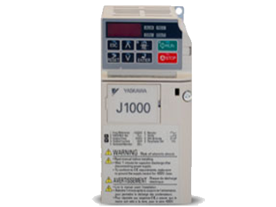
J1000
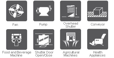
The J1000 meets all automation requirements for compact applications with variable speed operation and energy saving characteristics. A wide range of useful functions upgrade your machine and offer great potentials
Features
- Compact – Sleek desing and side by side installation
- A Breeze to operate – Easy parameterization with quick setup Mode.
- Environmentally friendly – Complaince with Eus RoHs directive
- Automatic torque compensation across entire speed range
- Stall Prevention Functions for stable operation during changes of load or power supply
- Auto speed search functionality
- Extensive Braking features
Main Application’s


Compact V/f Control Drive
- 200 V :
>1 Phase : 0.1 to 1.5kW
>3 Phase: 0.1 to 3.7 kW - 400 V:
>3 Phase: 0.2 to 3.7 kW
200V Single Phase
| J1000 Model number | PND(kW) | IND(A) | PHD(kW) | IHD(A) |
|---|---|---|---|---|
| CIMR-JTBA0001BAA | 0.2 | 1.2 | 0.1 | 0.8 |
| CIMR-JTBA0002BAA | 0.4 | 1.9 | 0.2 | 1.6 |
| CIMR-JTBA0003BAA | 0.75 | 3.3 | 0.4 | 3 |
| CIMR-JTBA0006BAA | 1.1 | 6 | 0.75 | 5 |
| CIMR-JTBA0010BAA | 2.2 | 9.6 | 1.5 | 8 |
200V Three Phase
| J1000 Model number | PND(kW) | IND(A) | PHD(kW) | IHD(A) |
|---|---|---|---|---|
| CIMR-JT2A0001BAA | 0.2 | 1.2 | 0.1 | 0.8 |
| CIMR-JT2A0002BAA | 0.4 | 1.9 | 0.2 | 1.6 |
| CIMR-JT2A0004BAA | 0.75 | 3.5 | 0.4 | 3 |
| CIMR-JT2A0006BAA | 1.1 | 6 | 0.75 | 5 |
| CIMR-JT2A0010BAA | 2.2 | 9.6 | 1.5 | 8 |
| CIMR-JT2A0012BAA | 3 | 12 | 2.2 | 11 |
| CIMR-JT2A0020BAA | 5.5 | 19.6 | 3.7 | 17.5 |
400V Three Phase
| J1000 Model number | PND(kW) | IND(A) | PHD(kW) | IHD(A) |
|---|---|---|---|---|
| CIMR-JT4A0001BAA | 0.4 | 1.2 | 0.2 | 1.2 |
| CIMR-JT4A0002BAA | 0.75 | 2.1 | 0.4 | 1.8 |
| CIMR-JT4A0004BAA | 1.5 | 4.1 | 0.75 | 3.4 |
| CIMR-JT4A0005BAA | 2.2 | 5.4 | 1.5 | 4.8 |
| CIMR-JT4A0007BAA | 3 | 6.9 | 2.2 | 5.5 |
| CIMR-JT4A0009BAA | 3.7 | 8.8 | 3 | 7.2 |
| CIMR-JT4A0011BAA | 5.5 | 11.1 | 3.7 | 9.2 |
| Control Characteristics | |
| Product | J1000 |
| Type | Versatile Compact V/f Control Drive |
| Rated Output Voltage (dependent on input) | Three Ph 200V Class : 200 to 240VAC Three Ph 400V Class : 380 to 480VAC Single Ph 200V Class : 200 to 240VAC |
| Motor Types | Induction Motor |
| Control Methods | V/f Control (V/f) |
| Speed Control Range | 1:20 to 1:40 |
| Starting Torque | 150% @3Hz for V/f |
| Frequency Range | 0 to 400Hz |
| Frequency Accuracy | Digital reference: within ±0.01% of the max. output frequency (-10 to +50˚C) Analog reference: within ±0.1% of the max. output frequency (25 ±10˚C) |
| Frequency Setting Resolution | Digital reference: 0.01 Hz Analog reference: 1/1000 of the maximum frequency |
| Output Frequency Resolution |
20 bit resolution at maximum output frequency |
| Accel/Decel time | 0.0 to 6000.0 s (2 selectable combinations of independent acceleration and deceleration settings) |
| Environmental Factors | |
| Ambient Temperature | -10 to +50˚C (open chassis), -10 to +40˚C (enclosure) |
| Altitude | Up to 1000 meters |
| Humidity | 95 RH% or less (no condensation) |
| Shock | 10 to less than 20 Hz (9.8 m/s2) max., 20 to 55 Hz (5.9 m/s2) max. |
| Area of Use | Indoors |
| Protection Features | |
| Motor Protection | Motor overheat protection based on output current |
| Momentary Overcurrent Protection |
Drive stops when output current exceeds 200% of Heavy Duty Rating |
| Overload Protection | Drive stops after 60 s at 150% of rated output current (Heavy Duty Rating) |
| Overvoltage Protection | 200 V class: Stops when the DC bus voltage is more than approximately 410 V 400 V class: Stops when the DC bus voltage is more than approximately 820 V (approx. 740 V when the power supply voltage is less than 400 V) |
| Undervoltage Protection | Thee Phase 200 V class: Stops when the DC bus voltage decreases to less than approximately 190 V Single-phase 200 V class: Stops when DC bus exceeds approx. 160 V Three Phase 400 V class: Stops when the DC bus voltage decreases to less than approximately 380 V(approx. 350 V when the power supply voltage is less than 400 V) |
| Momentary Power Loss Ride-Thru |
Stops when power loss is longer than 15 ms. |
| Heatsink Overheat Protection |
Thermistor |
| Stall Prevention | Separate settings allowed during acceleration and during run. Enable/disable only during deceleration |
| Ground Fault Protection | Protection by electronic circuit |
| Charge LED | Charge LED illuminates when DC bus voltage is less than 50 V. |
| Standards Compliance | ・UL508C ・EN61800-3 ・EN61800-5-1 |
| Power Specifications | |
| Rated input Voltage/Frequency | 400V Class: ・Three-phase AC power supply 380 V to 480 V 50/60 Hz ・DC power supply 510 V to 680 V 200V Class : ・Single-phase or Three-phase AC power supply 200 V to 240 V 50/60 Hz ・DC power supply 270 V to 340 V |
| Allowable Voltage Fluctuation |
−15% to 10% |
| Allowable Frequency Fluctuation |
±5% |
| Common Specifications | |
| Multi Funcction Digital Inputs | 5 Digital Inputs ( NPN or PNP ) , 24VDC. |
| Multi Function Digital Outputs | 1 Programmable Relay with MA-MB-MC (250 Vac, 10 mA to 1 A;30 Vdc, 10 mA to 1 A) |
| Multi Function Analog Inputs | 1 Multi Function Analog input A1 (0 – 10 V (20 kΩ), 4 – 20 mA (250 Ω)/0 – 20 mA (250 Ω)) |
| Multi Function Analog Output | 1 Multi function Analog output AM-AC (0 – 10 V, 2 mA) |
| Optional communication Protocols | RS232C, RS422/485 |
| Additional Functions | Momentary power loss ride-thru, Speed search, 9-step speed (max), Accel/decel time switch, S-curve accel/decel, 3-wire sequence, Cooling fan on/off switch, Slip compensation, Torque compensation, Frequency jump,Upper/lower limits for frequency reference, DC injection braking at start and stop, Overexcitation braking, Fault restart |
